Copper Headed Rail
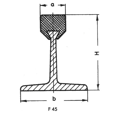
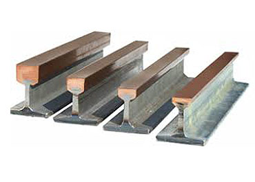
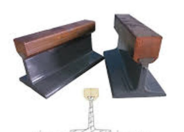
The Copperhead Conductor Rail was DEVELOPED in India by P. MITRA, the founder of IEP and we at IEP developed many railway systems. The "T" or "Hollow T" section and the extruded copperhead is drawn through a special die which compresses the copper flanges around the dovetail head of the rail, connecting the two components to a 100% rigid unit.
These conductors have proven an outstanding success for safe power feeding of : Travelling cranes, Loading bridges, Container handing equipment, Monorails, Hoists, Coking machinery and many other application. The Copperhead Conductor Rails are available in sizes to meet individual current requirements from 200 to 4000 Amps. This system is installed in SAIL R.S.P., SAIL BSP, Bhushan, etc.
The main users are : Steel mills, Coking plants, Gas works, Cement industries, Ship yard and Dockside enterprise, Transit and People Mover System.
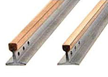
SOME ADVANTAGES OF IEP RAIL SYSTEMS
With IEP Systems you can eliminate all drawbacks inherent in the conventional design of trolley wires, steel angles and steel rails.
Adequate Ampere Capacity must be provided to carry the anticipated electrical bads.
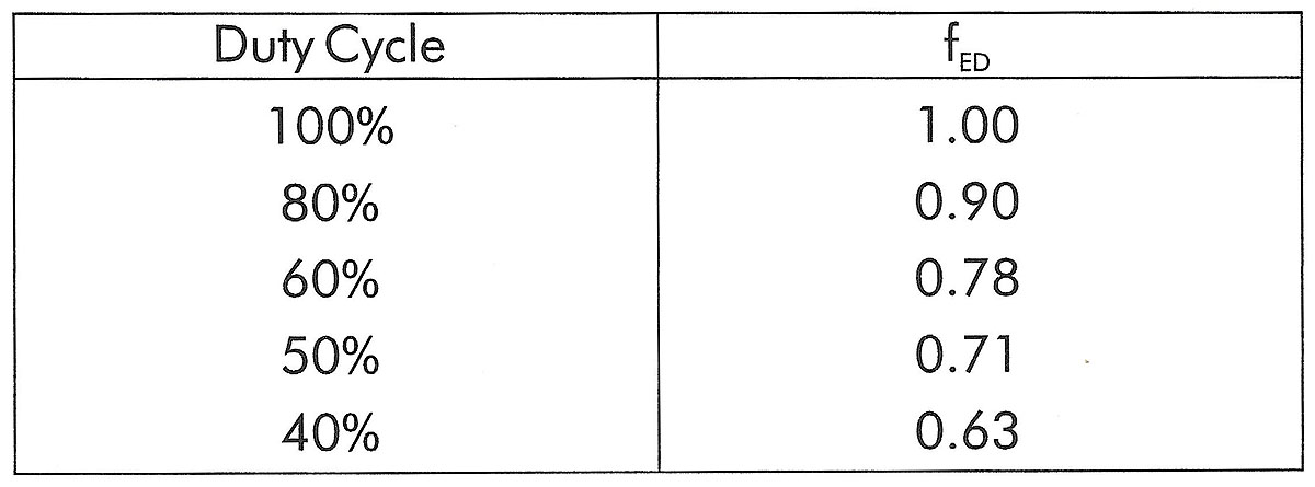
Total Ampere load is determined from the nominal rated full load current reduced by the duty cycle (/ED) and a diversity factor for non-simultaneous operation. The average crane motor duty cycle is usually between 40% and 60%, depending on the type of application. A diversity factor of 0.4 to 0.7 can be used when there are more than one crane on the same runway.
Example:
3 cranes, each In = 300 Amps.Length of runway: 100m (330')
Assumed duty cycle: 60% (ED)
Assumed diversity factor: 0.7
Ampere load per crane: InxfED=300AX0.78=234 A
Ampere load for 3 cranes = 234Ax3 = 702 A
TOTAL Ampere load when using a diversity factor of 0.7: 702Ax0.7 = 491.4 A
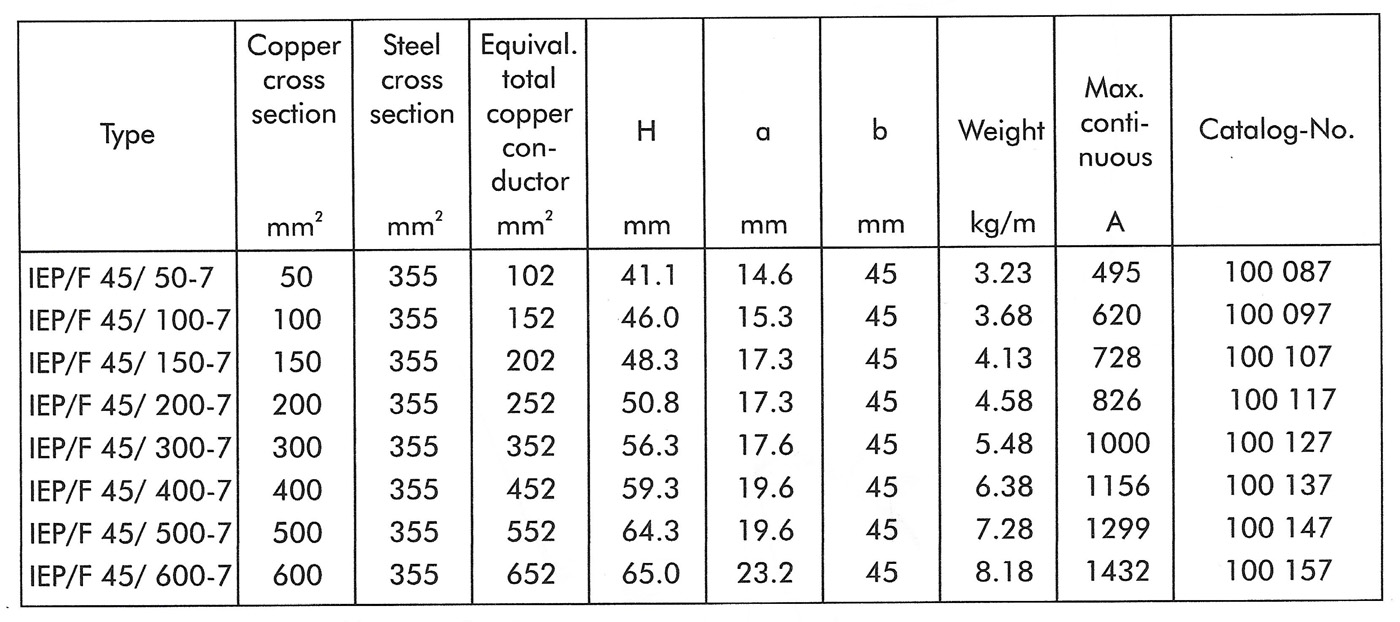
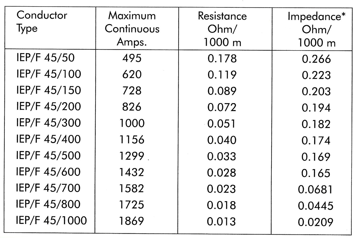
Selected conductors: F35/100
or F45/50
Formula for Voltage Drop Calculation
AC: ⃤ u = √ 3 x 1 x 1 x z
DC: ⃤ u = 2 I x 1 R
⃤ u = Voltage drop [V]
R = Resistance [ohm/m]
I = Ampere load [A]
L = Length from Power feed to end of conductor [m]
z = Impedance [ohm/m]
L = System Length [m]
Selection of Conductors
Other Criterion:
Effectice Length
I=L power feed located at the end of the systemI=L/2 power feed located at the mid-point of the system
I=L/4 power feed located at both ends of the system
I=L/6 power feed located at L/6 from each end of the system
Engineering Data
STEEL - COPPERHEAD RAILS
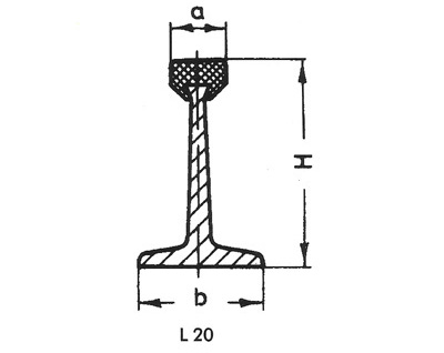
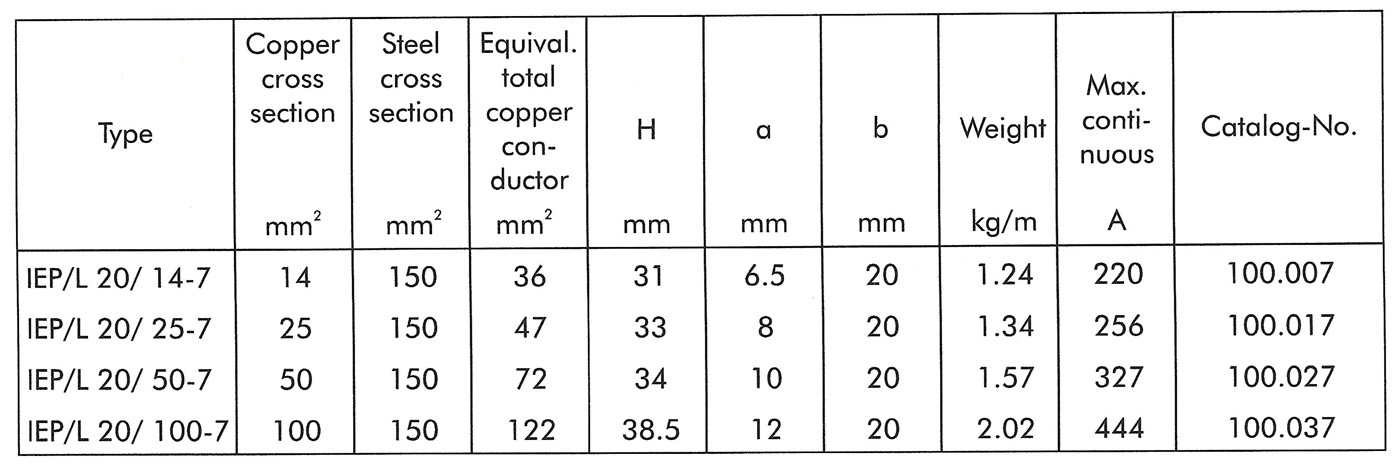
Standard Lengths:
7 m (23')Main application:
Conductor system for hoists and monorails, down-shop and cross travel supply for light cranesBest applicable collectors:
IEP/DVD 1 and IEP/DVD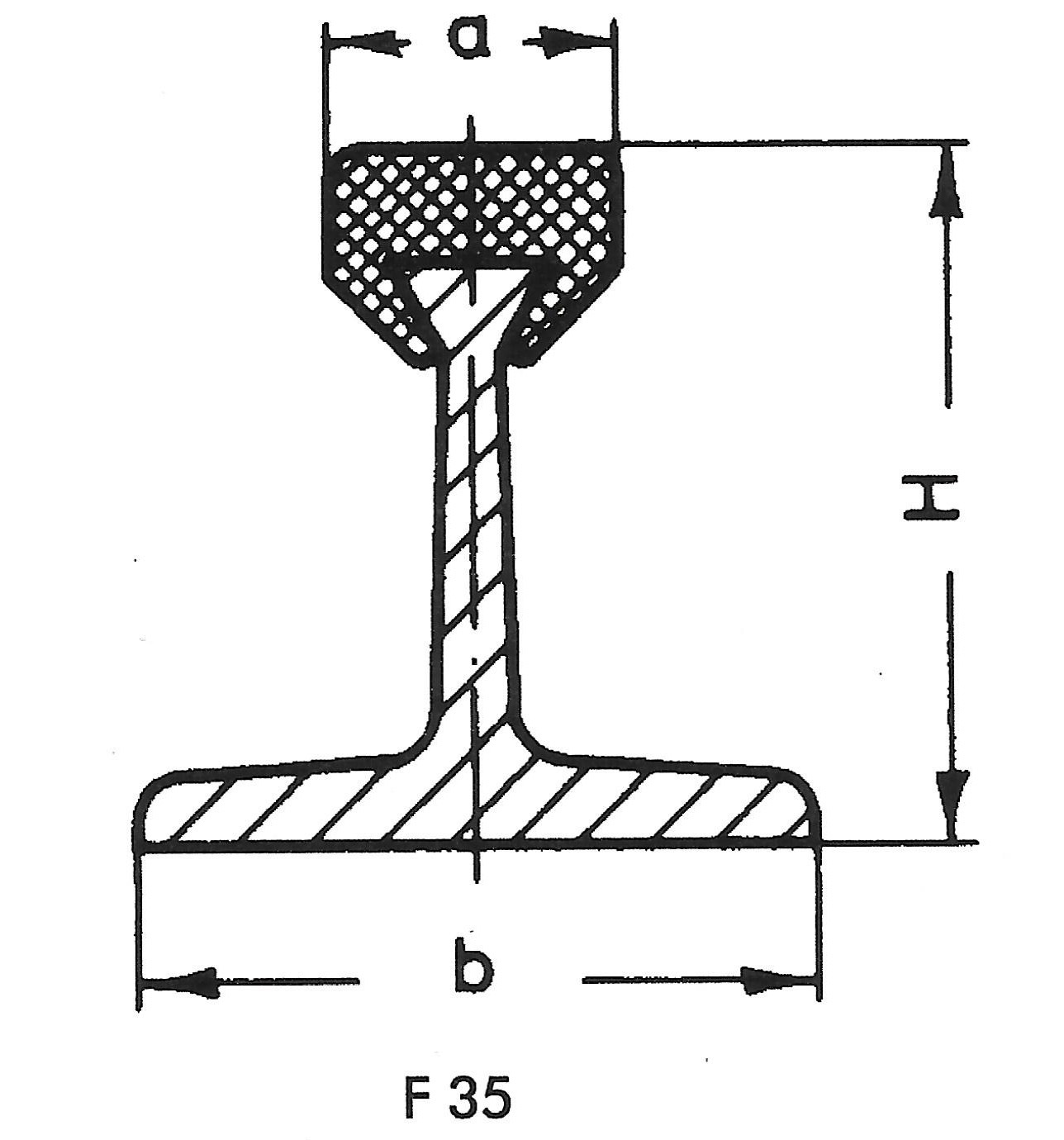
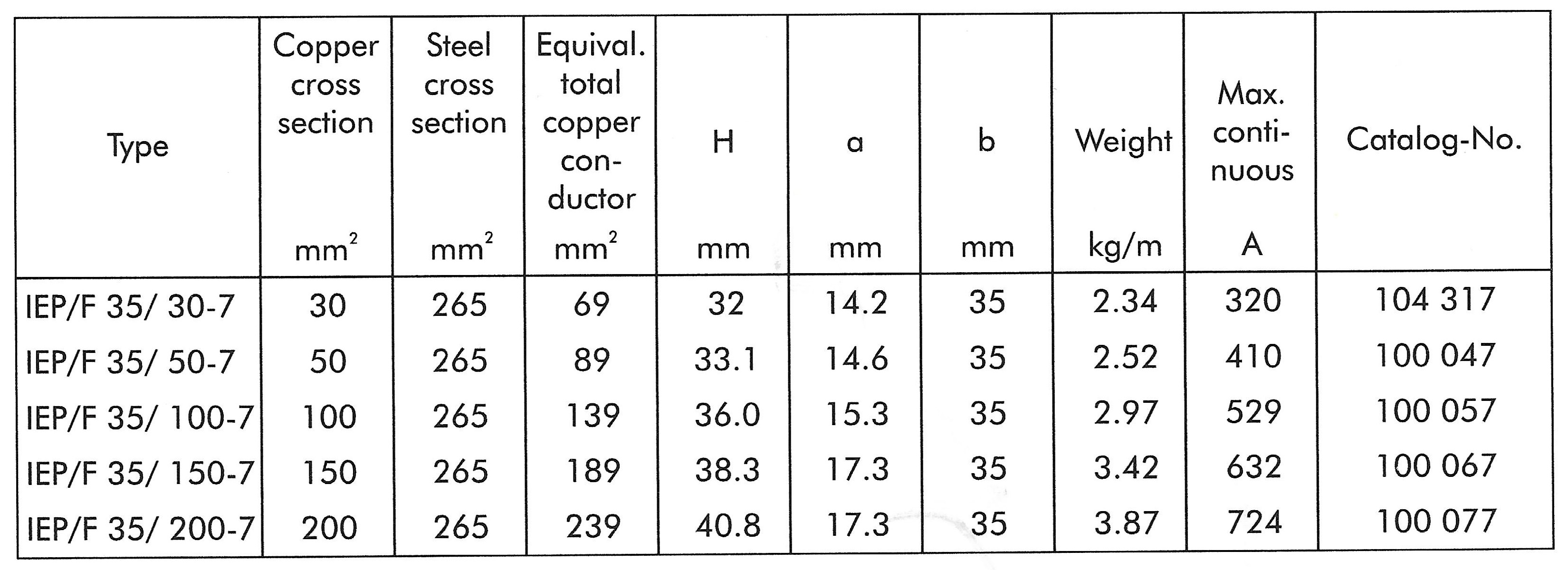
Standard Lengths:
7 m (23')Main application:
Conductor system for heavy and monorails, down-shop and cross travel supply for medium duty cranesBest applicable collectors:
IEP/GSV 1, IEP/GSV 2, IEP/GSV 4 and IEP/GSV 8